| Tue
26 Jun 2007
I've run out of both oxy and acetylene so
it's into town again. I also have to drop off some steel to be cut
for the body mounts, at 32mm thick it's too much for my emerging oxy-cutting
skills, I could possibly give it a go but they have to be done right
so I think I'll let the experts do it.
I also have to make a home brew today or I'll
be in dire straights in about two weeks when I run out of beer.
The trouble is it's so damn cold, how do I keep
the brew warm for the first week or so as it ferments? Normally
we use our electric blanket, but we haven't brought it with us,
so some ingenuity is called for.
I find a cardboard box large enough to enclose
the barrel, wrap it with as many towels as I can find to insulate
it, then put the barrel of fermenting beer inside. This is a good
start, but insulation is not the full solution, something has to
top up the temperature every now and then.
I get my heat gun and stick it's nozzle under
the box, it's rated at 600 degrees so that should do the trick.
It works well, although a small fire necessitates a design modification.
I find a length of 40mm PVC pipe from the old truck's sink, insert
it under the box and blow the hot air in through that. This keeps
the hot nozzle away from the towels.
After that I make a start on the rear body mount.

Some of the components for the rear
body mount being marked up.
Thu 28 Jun
Still working on the rear body mount.

The rear body mount partly tacked
together.
Sat 30 Jun
Finally the rear body/shockie
mounts are done. It's taken longer than I figured but I've had my
usual quota of dramas, like the mount wouldn't fit back onto the chassis.
I can only assume that it pulled when I welded it, even though I did
most of the welding with it in place on the chassis, only doing the
underneath welds on the stands.
To get it back onto the chassis I have to cut
halfway through the mount to allow it to stretch, then get everything
bolted on, and finally weld up the cut.
Throw that in with bottling of the home brew,
running out of both water and battery power and therefore having
to juggle the pump and generator (The pump uses a lot of power but
the batteries are not that charged, I'm charging them with the generator
but the pump won't run while the generator is because there's some
incompatibility between the two).
Then the inverter overloads, even though there's
bugger-all running from it, so I have to isolate it from both the
solar array and the batteries to reset it (no reset button that
I can see), this also resets the solar regulator and all its memory,
so I now have no idea what state of charge the batteries are in.
Then the can of cold gal is blocked and won't
spray, etc etc.

Here's the plan.

And here's the final thing. The rectangular
tube near the centre and the openings on the right side (shown in
red in the plan) will allow the winch cable to pass through the
mount. The tube had to be custom made from scrap because I didn't
have any RHS of the right size to hand and it was either that or
drive into town yet again. The sqaure block in the middle with a
large hole is a cut-down piece of a mount from Wothahellizat 1

A close up of one side of the mount,
showing the outrigger that will hold the shockie and an original
bump stop in place.

Another close up, this time one of
the front (ie middle axle) shockie mount.
Sun 1 Jul
Since I'm working on the
body mounts let's talk about that for a while.
With Wothahellizat 1 I used the triangle method
(discussed soon) and it worked very well as is displayed in this
photo.
Trials of the body mounting on Wothahellizat
1.
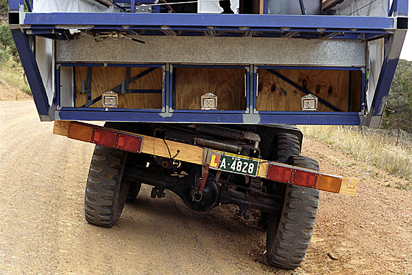
This is a shot I took of Wot 1 when we were doing
some trials about seven years ago. Note the board with the number
plate and lights, it's in line with the chassis and the rear wheels.
The front wheels are at almost the same angle but in the opposite
direction, and the body is somewhere in the middle.
I think this demonstrates very well how much the
chassis can flex on some trucks, and this isn't serious off-roading,
it's just a drain on the side of the road.
There are two things to think about when mounting
the body, how to mount it, and where.
How
Ten years ago I looked around for a suitable mounting system and
found these.

There are three parts per mount,
seen here as purchased.

And as used
They are made in England and available from Shock
& Vibration Technologies in NSW, I can't find a web site for
SVT but the mounts are made by Barry Controls at www.barrycontrols.com.
These mounts are designed for off road equipment and large trucks,
which is why I chose them in the first place.
You buy the two rubber donuts and the steel donut
from SVT, then weld the steel donut into an appropriate place on
your mount, sit the body on top of the rubber donut, and fasten
the whole lot together with a big bolt.

Cross section through a typical installation.
Do this in the right places and you have a mounting
system that can absorb the twisting plus isolate the body from much
of the road vibration.
After all that time carrying the weight of the
old body the rubber donuts don't look as pristine now, but they're
still in good nick so I'll be reusing them.
I originally had the steel donuts welded into
some large 32mm plates, but they were way too big for my current
design and I had them cut down to 170x200mm blocks the other day
(seen clearly in the photos of the rear body mount).
Where
There's two methods of mounting a truck body onto a flexible chassis,
two recommended by the Department of Transport that is.
These methods are called diamond and triangle,
and they allow the chassis to twist without placing undue strain
on the rigid body. If the body is a tray that is fairly flexible
I don't think it matters much how you mount it, but a motorhome
body is a box that is pretty rigid. If it's not then all your cupboards
will deform, so we have to isolate that rigid body from the flexible
chassis.

The two recommended methods of mounting
a body, diamond (top) and triangle.
As stated I used the triangle method on Wothahellizat
1 and that worked well, but I've decided to go with the diamond
method with version 2. This is because it will distribute the weight
more evenly. The new body is not as strong as the old one so it
seems reasonable to support it in more places.
Mon 2 Jul
Another thing about using the diamond pattern is that I should only
have to allow for half the total chassis twist.
With the triangle method the chassis and body
are fixed together at one end so the clearance at the other end
has to handle the entire twist, 10 degrees in the case of the old
chassis.
The diamond is effectively two triangles. As the
chassis and the body are tied in the middle, the same 10-degree
twist amounts to only five degrees at each end.
Throw in the fact that the chassis is now shorter
and we should be better off all around.
That's my theory anyway, and I'm sticking to it.

The middle body mounts ready for
welding.
Tue 3 Jul
All the mounts on the rear of the chassis are finished now.

The rear of the chassis showing the
rear body/shockie mounts (rear), front shockie mounts (middle) and
middle body mounts (front). Confused? Also you can see the rope
I've stretched to simulate the winch rope.
Now I just have to do the front body mount and
I can put the body back on.
Wed 6 Jul
Today I start building the front body mount. It's pretty much a
replica of the rear mount but has no provision for shock absorbers.
It's the usual story of cutting and bending steel
and drilling a lot of holes. I run out of acetylene so decide to
do the drilling instead. That will fill in the rest of the day and
I'll get some gas tomorrow.
With a high-torque drill you have to pay a lot
of attention as the minute you lapse it will rip your arm off. It's
nearing the end of the day and I'm getting tired so while drilling
a 13mm hole in a difficult-to-access location on the chassis I decide
stop, rest, and change my grip.
Unfortunately I do it in the wrong order, ie.
I relax my grip before stopping the drill.
Result, bit grabs, drill spins, drill tears from
my grasp, drill's still spinning with entire weight on drill bit,
bit breaks leaving it's end embedded in the hole, drill falls to
floor.
All in all not a good result.
Fortunately there's no damage to the drill itself,
but the bit is knackered and I have to remove the broken part form
the hole.
Thu 5 Jul
Still building the
front body mount. I've also had to modify a winch cable roller mount.
I have the same problem with this mount that I had a few weeks ago
with the compressor hanger, that is, once the air receiver is in place
I can't get to the inside of the chassis to access the other end of
the mounting bolts with a spanner. So I make a backing plate similar
to that previously described, to it I weld two nuts and two bolts.
Why this combination?
The mount itself requires three bolts and because
of the clearance between it and the roller two of them have to have
the bolts inserted from the outside ('A' in the drawing). So these
two at least have to have nuts welded to the plate. The third one
could as well, but this would leave the plate hanging on the locating
bolt when the mount is removed, and if it rotated it would be very
difficult to realign it.
Therefore I make the plate to provide me with
two captive nuts and a captive bolt ('B' in the drawing), plus the
locating bolt. This gives two bolts protruding from the chassis
to stop the plate rotating when loose, and two nuts inside the chassis
to which I can screw bolts from the outside.

A cross section of the new captive
mounting nuts and bolts for the winch rope roller. Note only one
bolt and nut shown.
Now I can remove/replace the roller at will without
having to deal with the receiver.
Finally I can weld up the body mount and put it
in place.

The front body mount in place just
behind the cab.

A side view. Once again notice the
asymmetric bolt locations, as much as possible I'm trying to use
existing bolt holes and if that means it looks a little odd then
so be it.
Then I have to replace the air receiver, it's
a bugger of a job for one person as you have to hold about ten different
objects at once, one of which is large and heavy.
Just as it is getting too dark to see I finally
get it all installed.
Fri 6 Jul
Now I can put body onto the chassis, I forget to notice the time
when I start so still don't know how long it takes to raise the
body on its legs, but it takes a while, maybe over an hour.

The body propped up in place. Note
the jack under the bumper bar at the front, this is to level the
chassis. There's another one at the rear.
With the frame in place I can start on the other
half of the body mounts, the parts that belong to the body. Before
I start though I have to level the chassis.
Over the years we've had various springs reset
at whatever weight (and distribution of weight) the truck was at
the time. Now, with no weight at all, the springs have risen to
different heights causing the chassis to have quite a twist even
when parked on a flat concrete floor.
I guess we'll have to have everything reset yet
again, but not until we have the truck finished and know the final
weights.
Meanwhile, If I want to get the body mounted in
the right place I have to level the chassis, which I do with some
jacks.
Sat 7 Jul
This morning I was all fired up to go into town and buy the four
bolts I need to hold the body onto the chassis. That way I reasoned
that I would have everything I need to finish the job over the weekend.
Then I realised it already is
the weekend. The bolt shop won't be open today so it will have to
wait.
Not that I haven't got plenty to keep me occupied,
I still have to make the other half of the body mounts, the parts
that will sit on top of the chassis's mounts and connect to the
frame.
To do this I planned to have some heavy steel
cut and drilled to sit on top of the rubber mounts, but then I realised
I can do the same job with some left over bits from Wothahellizat
1 and a piece of scrap steel
I weld a 1" nut to one of the old snubbing
washers.

Then place a 200mm square 12mm plate with a large
hole cut in the centre over the nut and weld that to the nut.

Then flip the whole thing over and weld the washer
to the plate.

This assembly, and three others just like it,
will sit on top of the chassis part of the body mounts and be welded
to the frame. They will provide me with four captive nuts in the
body.

A cross section through a body mount.
The circled area is the assembly shown in the photos above.
Sun 8 Jul
The mounts are in place on top of the chassis mounts, but now I
have to decide exactly how to connect them to the frame, and I confess
to being at something of an impasse with this.
I've drawn the frame as just two 3x1" RHS
pieces ( in the diagram)
but I can't sit the entire weight of the body on just two pieces
per mount. in the diagram)
but I can't sit the entire weight of the body on just two pieces
per mount.
I spend a lot of the day thinking about this and
consulting the computer design before eventually starting to cut
some steel.
Mon 9 Jul
Every time I watch a current affairs or news program these days
I hear of the desperate labour shortage in the remote mining areas
of Australia.
Invariably a person or two are pushed in front
of the camera and say a variation of, "I used to work my arse
off for $3.50 a day, now I get paid $100,000 to drive an air conditioned
dump truck".
Heck, we've even met people like this. But when
I do a web search for these fantastic jobs I get zero results.
Try it, Google "dump truck driving job western
australian mines". You'll get a lot of results pointing to
BHP Billiton's career pages, and all manner of employment agencies
and at first you think you've hit pay dirt.
But drill down and all the jobs are for senior
geologists, mine safety officers, and drill & blast professionals.
Or you need experience...
"Applicants must have at least 6 months or more experience
on CAT 785, 789 or 793's for the dump truck role"
Not one job for an unqualified grunt can I find.
And yet "they" all say they will train you, "We've
got people here from all walks of life" says a fellow on 60
Minutes last Sunday.
But maybe it's like it was in the 70's, you had
to be on the spot. When I was living in Perth 30 years ago it was
a given that there was no point applying for jobs from the capital
city, you had to drive up to the mining towns. Well possibly, but
a year ago we were in Tom Price, one of the main mining towns and
smack in the middle of the Pilbara. You couldn't get any more central
to the iron ore mining industry if you tried.
We enquired at the local employment agency and
were told there was nothing at present.
Of course we're not in a position to get such
a job now anyway, but should be in a few months so I decided to
ask the people at CareerOne, probably Australia's largest agency.
I filled out their enquiry form.
Hi,
For a year or so now we hear just
about every night on the TV that the mines are crying out
for workers of any kind. One of the most often cited examples
is that of dump truck drivers. Just the other night some talking
head said that there is 100 jobs of this type in Tom Price
right now.
My question is, where are these jobs
advertised? I cannot find a single job for a relatively unskilled
(in this field anyway) worker. All that is advertised are
professional career positions. |
We'll see what the response is, if any. Meanwhile
I did a search on their site for "dump truck driver" and
got one result, for a bloody IT manager in Perth.
Later...I get a response but I'm still none the
wiser. The link they suggest has hundreds of truck driver jobs,
none of which are on mines or in Western Australia. There's tilt
truck drivers in Sydney, cement truck drivers in Melbourne, garbage
truck drivers in who-knows-where.
But NO dump truck drivers on West Australian mines.
It's no wonder there's a shortage of labour, no-one
can find the jobs.
As I said we're not in a position to follow up
on a job opening anyway, so I'll leave it at that for the moment.
But in a few months time I will revisit this issue so watch this
space if you're interested.
Conversely, if you know who to approach let me
know.
Wed 11 Jul
I've run out of steel of the size I need to finish the body mounts.
I have ordered more but I have to wait for Mick (he and his family
are between houses and living in the "house" part of the
workshop) to bring it home from work.
He owns the engineering business I get the steel
from, and often brings stuff home for me in his ute or even brings
the truck. It's a good arrangement as it saves me the delivery cost
which would not be cheap out here, but of course I can't demand
when things are to be delivered. So I have to wait a day or two.
No matter, I've started on the tool boxes.
I've decided to hang some toolboxes on the chassis
and in between the rear axles. These will house some of the heavy
stuff like ground anchors, jacks, snatch block, the bead breaker
(for changing tyres) etc. This stuff is very heavy and as I'm trying
to get as much weight as possible over the rear axles it makes sense
to build storage for it there.

The half-fabricated toolboxes. The
triangular infills are there to provide strength to the front of
the box, but also if the door was the full front of the box it would
hit the wheels and not fully open.
Thu 12 Jul
The toolboxes are turning into quite a project.
At around five I get a call from Peter, he's in
Katherine with a faulty fuel shutoff solenoid. Can I pull the one
off his old motor and freight it up to Kununurra in WA where he
will pick it up in a few days.
Fri 13 Jul
I ring to see if Mick can deliver the steel today but it doesn't
sound likely, so I volunteer to do the job. I drive into town, post
Peter's solenoid, then go around to Reibelts Engineering.
The truck is loaded with junk for a job so the
first thing I have to do is unload it. Then I can put my steel on
and drive up to the workshop.
All this, plus getting a gas bottle filled, takes
about four hours, I won't get much done today.
Sat 14 Jul
I'm struggling a bit over the way to connect the body mounts
to the actual body. The theory is simple enough, just weld them
to the frame, it's easy when you say it fast.
But exactly what gets welded to what, and how
do I make everything strong enough?
I start with the mounting points ('a' in the drawing
below) of course, then weld in some basic connections (b) to the
existing frame and follow up with more to strengthen strategic points
(c).
In general I'm happy that this has spread the
force pretty well from the mounts out into the frame.

Mouse over the legend text to see
the different levels of mounting and bracing (animation not working
at present).

The rear mount and associated framework.

One of the middle mounts.

And the front mount.
The reason there is so much steel at the back
of the frame (in the rear mount photo above) is that there will
be a lot of weight there. This is the lounge room which has the
double whammy of having to support 800kgs (1800lbs) of water in
tanks, and a 100-odd kilogram motorbike with very little structure
as the walls are large shutters and therefore almost entirely void
space.
To help support all this I've also added some
bracing (d) in the form of 75x6mm flat bar welded vertically under
(or over depending on the access) some of the frame RHS. This will
double the web depth of the selected members and therefore presumably
double the strength.

Some 75x6mm bracing under one of
the frame's cross members.
Sun 15 Jul
Dave dropped in this morning to see how things are going. He cast
his expert eye over what I'd done and asked a couple of questions
but as usual didn't comment much, except to say "It's gunna
be strong then", which I'll take as an approval.
Tue 17 Jul
I've added gussets to each mount, mostly because I can, and partly
because I just want to ensure things are strong enough.

Looking down into one of the mounts,
showing the four triangular gussets.
The trouble with not being an engineer is that
I have no way to calculate the stresses, so I just make something
so it looks about right, then add a bit.
It seems to work although I often make things
too strong, and therefore too heavy. However the alternative is
to make them too light and weak so, within reason, I'll go for heavy.
The last Wothahellizat body was extremely heavy,
but it never even looked like breaking. Here's hoping this body
will stand the test of time.
One of these mounts is underneath the shower base
and I had planned to put an inspection panel in the shower in case
I ever needed to check out the mount. The trouble with this is that
should the panel ever leak the mount will fill with water and I
will not know.
Dave suggested a good idea the other day though,
forget the panel and fill the mount with grease. As there is nothing
to inspect apart from a captive nut, and that will be covered with
grease and unable to rust, there should never be a reason to inspect
it.
I still feel a little uncomfortable never being
able to view the top of the mounting bolt though, and I may want
to add a lock nut to the top of the mounting bolt, in this case
I will need access.
We'll see.
Wed 18 Jul
Without the steel to finish the mounts I've
been working on various parts of the body.
I've added much of the support for the floor and
should be able to lay that before long. I've also built some of
the crawl through from the cab.
|