| 10 Jan 2000
Something of a milestone was passed today,
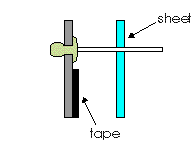
the first sheet of cladding was installed. For those who don't believe
we are cladding the motor home with checker plate here's a photo
of the first sheet.
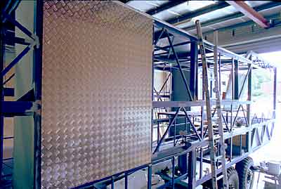
The first panel of checker plate
is attached.
That's 2mm aluminium checker plate, it is fairly
heavy and will look weird but it will take a hammering and that's
what I want.
So how is this sheeting attached? Pop rivets?,
tech screws?, Sikaflex? None of the above. It relies entirely on
double-sided tape.
That's right, double-sided tape. But this is not
your average hardware store mirror tape. It's 3M VHB (Very High
Bond) and believe me, this stuff sticks. When I asked the 3M rep
what I do if I make a mistake placing the sheet he simply said "You
don't make mistakes".
Apparently the minute you press the sheet a 20%
bond is created. At this point you need an air chisel to remove
the sheet (destroying it in the process).
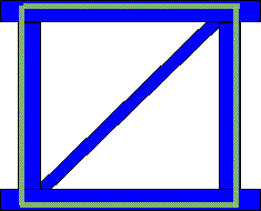
So the first thing we needed was a method of placing
the sheet in exactly the right place. Bob and I came up with a solution,
as follows...
Step 1. Shape the sheet as required then
clamp it in position.
Step 2. Drill two or three pilot holes
large enough to allow a pop rivet mandrel to be inserted.
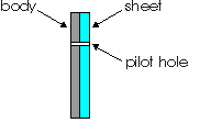
Step 3. Remove the sheet and enlarge the
holes in the body to a size appropriate for the pop rivet body.
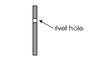
Step 4. Insert pop rivets and hand pull
so the rivet is firm, but don't pop. This will leave the mandrels
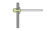
sticking out from the body, thus creating some locating pins.
Step 5. Prepare the body for your VHB (I'll
describe this later).
Step 6. Press the tape to the body and
peel back the non-stick backing slightly from each strip of tape.
Stick the backing to one side with masking tape.
Step 7. Hang the sheet on the mandrels
ten or so mm off the tape.
Step 8. Starting at one end/side or the
middle as appropriate for the situation, remove the backing entirely
and press the sheet home.
Step 9. Now pop the rivets leaving them
behind the sheet.

Step 10. Fill the small locating holes
if you feel it's necessary.
There, that was simple wasn't it. Now what about
preparing the body for the VHB tape.
If possible remove any paint, loose material etc
then clean the areas to be taped with the appropriate 3M cleaner
(I think you can use hydrocarbon thinners but I decided to use the
official cleaner).
You should have a large supply of clean, lint-free
rags for this job. The cleaning should take the form of a single
stroke on each section of rag. Once you've wiped with an area of
the rag it is dirty and should not be re-used. Also do not rub backwards
and forwards as this simply moves the dirt from one place to another.
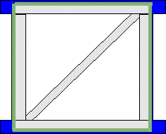
This should leave you a nice clean steel frame,
something like this...

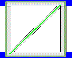
Now add the VHB tape...
Note that I haven't taped the cross member, I
don't think it's necessary to tape everywhere and besides, VHB is
very expensive (about $1.25 a foot). However this depends on the
sheet size, larger sheets may need to be taped through the middle.
I plan to paint the entire interior with the Barrier
2000 insulating paint but if I'm not careful there will be some
Achilles heals. The small areas behind the sheet that are not covered
with tape, if these are not painted now I will never have another
chance.
Now I add a bead of sealant to
the cross member so there is no metal-to-metal contact to
cause noise and possibly electrolysis.
Once the sheet is applied I run sealant around
all the joints at the back and, eventually, paint the entire inside
with Barrier 2000.
Note: Diary
#24 has more info about using the VHB tape.
16 Jan 2000
Move over Eiffel tower, stand aside Sydney
Harbour bridge, the Golden Gate?, child's play. Of the many steel
marvels in this world the rear steps of my motor home must surely
be the most astounding.
The steps took on a life of their own, taking
a couple of weeks to complete (not full time though). Still, as
the entry point to the lounge room is two metres from the ground
the stairs have to be a fairly serious affair.
Here is the computer drawing of the stairs.

The hardest part was determining the locations
of the pivot points for the top step and the link from there to
the body. Here is some detail of that area.

The top step is fixed to the body. The second
step is controlled by the top link (both shown in raised and lowered
positions). Various other constraints caused the pitch between the
top and first steps to be different to that of the rest of the steps,
therefore the position of the top pivot point was not a no-brainer
as it would have been if all steps where equal.
Once I got the top step working it was a fairly
simple matter to hang the other seven parallel to the first.
There are eight steps in all, they collapse to
a height of about 60mm when raised and stay parallel as they lower.
This is so we have horizontal steps regardless of the distance the
stairs get lowered due to different ground levels (Ok that's my
excuse, really I just wanted the challenge, and besides they look
great).

|

|
|

|
|

|
|

|
|

|
| This
is a semi-animated JPEG, place the mouse on a
number to load the sequence images showing the
steps in action. The first time may take a few
seconds, after that it will be instant. |
|
|
|
|
Originally I was going to used hydraulics to raise/lower
the stairs but decided that a winch was easier and more appropriate.
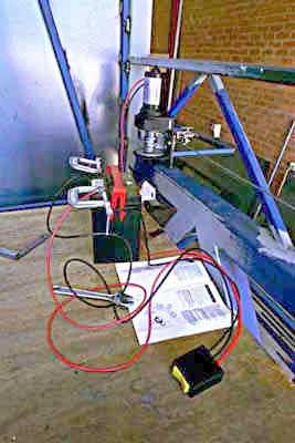
The winch in its original location.
Above we see the original location
of the winch, in the lounge room. The trouble was this particular
winch (a Superwinch T1500) is unbelievably noisy and this
location does not lend itself to much soundproofing as this
would encroach even more on our lounge area. I moved it under
the floor.

The winch after being moved to
an under-floor location.
After re-installing the winch it worked well but due to a slight
miscalculation in angles the cable bunched at one end of the spool.

The uneven winding of the cable
causes the steps to drop unexpectantly.
At first I thought this wouldn't matter but I
soon realised that it did.
As the cable wound onto the spool it built up
about four layers of itself then the top layer or two "fell
off" causing the steps to jerk downwards a few inches. Not
a catastrophe but disconcerting and the resultant shock load may
have caused problems in future.
Originally I figured to add another pulley to
redirect the cable, then I reasoned that if the new pulley was spring
loaded it would remove any sudden shocks from the system and help
keep some tension on the cable when the steps were lowered.
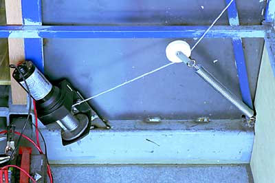
The winch with its new spring
and pulley (or "sheave" as they are more correctly called).
I installed the pulley and spring then realised
that there was another benefit to this spring loading.
As the stairs raise and the geometry changes they
effectively get heavier, this in turn causes the spring to extend
and the cable to "walk" up the spool thus producing a
very even winding.

The cable winds evenly onto the
winch's spool.
Once raised a pinchweld seal is engaged and
the load is taken off the winch by a cam lock.
As mentioned, the winch is incredibly noisy and
will need to be boxed in and soundproofed but, all-in-all, the system
seems to work well.
|