| Wed
23 May 2007
Today I started working on the spare wheel
carrier. The spare wheel and an extra tyre will be housed behind the
cab on the right hand side. I've designed a method of hanging them
that also uses the majority of the void space (inside the wheel hub
and spare tyre) for storage. More about that later if it works.

My workbench-on-wheels (left of
shot) I made before starting on the project is working well, I can
wheel it around to be next to the part of the truck I'm working
on.

Marking out one of the steel pieces
used to make the spare wheel carrier. Note the dividers, these are
invaluable for transcribing measurements from one place to another,
typically the chassis to a piece of steel or vice versa.
I had some of the circular pieces of steel cut
by a local engineering firm because the radius was too large for
my gear. Unfortunately the heat has caused one of the pieces to
warp and it has taken me a while to straighten it.
Also I had to fix one of my own stuff ups. I'm
sure I must be numerically dyslexic because I seem to always transpose
numbers. For example, today I measured the distance between two
holes on the chassis as 289mm but drilled the matching steel plate
with holes at 298 centres. And yes I did measure twice.
Fortunately with steel this is usually just an
inconvenience as it's easy to fill the hole with the welder and
redrill.
Fri 25 May
Today has been a very frustrating day trying
to juggle various generators and pumps. The power and water system
here requires constant monitoring to ensure things are working properly,
and today things aren't, working properly that is.
As rain is forecast for the next few days I thought
it prudent to pump water up to the top tank from the main storage
tanks. This will free space in the main tanks to accept the imminent
rain.
So I start the small generator and start the pump.
The generator has a fuel leak so I stem the majority of the flow
buy clamping the filter bowl with a hose clamp and put a container
underneath to catch the rest. Everything else looks fine so I get
back to work. After an hour or so I decide to check how things are
going.
The pump is making a noise and so I assume it's
pumping. However the main tanks are overflowing which implies that
the top tank (on top of a nearby hill) is back flowing into the
main tanks. I switch off the pump and the sound doesn't change.
What is happening is that the back flowing water is running the
pump in reverse.
I recheck all the circuit breakers and cannot
find any problems so walk back down to the pump the turn it back
on. Sure enough it starts. Ok whatever, it's working now.
I return to work.
After another hour I check again to find exactly
the same thing happening again. Aargh!
I repeat the process of cycling power but this
time hang around to try and sus the problem.
Eventually I decide that the pump does not like
the power provided by the small generator, at $1300 for a 5kva generator
one has to wonder about its quality, and in fact I've been suspicious
of it for some time now.
My theory is that the power is unclean and this
causes the pump's motor to overheat and throw it's thermal cutout.
That's why it starts up again after I muck around with things for
a while.
It looks like I have to start the big generator.
At 6.5 litres an hour fuel consumption I'm loathe to run it unless
absolutely necessary, but we have to pump water. I do need the large
gennie to do some welding with the three-phase welder, but that
will only take half an hour or so.
I start the generator and restart the pump. After
ten minutes the tanks stop overflowing, yes, I'm finally on a winner.
I get back to work.
A few hours later I ride up to the top tank to
check the level. It's 700mm from the top, that will take about 80
minutes to fill and as I have to go back into town to pick some
bolts in an hour and a half that should work out well. I'll shut
everything down before I go.
Meanwhile we're getting almost no battery charging
done because the charger keeps throwing its circuit breaker. So
at approx $7 an hour I'm only getting water pumped when I should
also be getting all the batteries charged. And now the battery charger
doesn't appear to be working at all.
Such is life. I shut down the generator and go
into town.
On my return the first thing I hear is the pump
running. Bloody hell, it's been running for an extra couple of hours,
there will be flat batteries and water everywhere. I stop it and
check the level of the main tanks. They have gone down as one would
expect, so I assume that the area around the top tank is swimming.
I ride up to check. Not only is it dry around
the tank but the level has dropped to 1300mm from the top. I am
now at my wits end, both tanks have dropped and there's no wet patch
in the middle. Where has all the water gone?
It's a very steep track up to the tank and on
my way down I bash my foot on a protruding log. I'm really starting
to get pissed off.
So, after all that, and about $40 in fuel, both
the batteries and the top tank are at approximately the same level
as they were first thing this morning. Ain't life grand.
Never the less I did manage to achieve something
today, I've made some progress with the spare wheel carrier.

The spare wheel carrier
propped in place on top of a jack.

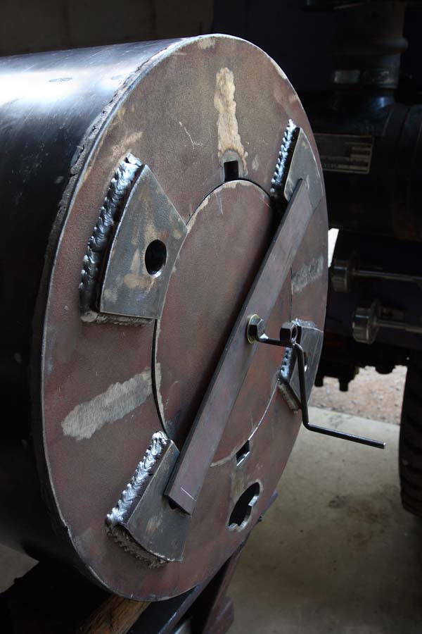
A close up of the front
plate. Note the four welded pieces, these act as spacers to set
the wheel hub away from the plate and also reinforce the mounting
points. Note also the cuts in the plate, I did these the other day
to allow me to straighten the warped plate, then decided to leave
them in place until I've finished the heavy welding so the heat
from the welds won't warp the plate again.

Exploded view of the spare wheel
carrier.
| A |
Chassis
rail. |
| B |
Chassis
plate and gusset: A piece of the old chassis
is used as an easy way to get a L-shaped piece
to wrap around the chassis. This gives me
somewhere to weld the strengthening gusset. |
| C |
Circular
back plate. |
| D |
Backing
ring: Sets the location of the tyre. |
| E |
Drum
with internal gusseting at the location of
the top two wheel mounting points. |
| F |
Spare
tyre: Has a spare tube and rust guard inside
and is held in place by the backing ring on
one side and the spare wheel on the other. |
| G |
Front
plate with captive nuts: This is what the
wheel bolts on to. |
| H |
Spare
wheel. |
| I |
Cover
plate: Allows me to use the centre of the
wheel hub for storage. |
Of course there's a lot more to the carrier than
is shown in the above drawing, I'm just trying to illustrate the
main parts.
I still have to devise a method of getting the
tyre and wheel up onto the drum. Currently I'm using the forklift
but we won't be taking that with us I suppose, although A-framing
it might not be a bad idea, it's a very useful piece of kit.
Sat 26 May
Still working on the spare wheel carrier. I've
welded the captive nuts and the internal gussets on to the rear of
the front plate. All this is done with the carrier bolted to my spare
rim, firstly to ensure that the nuts are in the right place, and secondly
because the rim will keep the plate held fast so it shouldn't distort
with the heat. I also welded the four cuts I made the other day.

The inside of the drum showing the
captive nuts and gussets.

The drum bolted to the spare wheel.
Having finished with the main parts for the time
being it's time to look at some details.
As mentioned the carrier will double as storage
with access through the large hole in the centre. I kept the piece
that was cut out to create the hole, and will use it as a "lid".
But cutting some notches in the front plate and
making some matching tabs on the lid I have created a sort of bayonet
fitting whereby I insert the lid and rotate it to hold it in place.
To lock it more firmly there is a cross bar that is tightened using
a bolt with a handle.
The lid with crossbar and tightening
handle. By tightening the handle the lid is pulled against the back
of the front plate and held firmly.
The handle is made with a short length of 6mm
round bar that has been bent to shape and welded to the bolt head.
The bolt in turn screws into a captive nut welded on the inside
of the lid.
The handle is asymmetrical which stops vibrations
from rotating it. If you have a symmetrical handle that is nicely
balanced vibrations can cause it to unwind. This handle's weight
should be more than the enough to resist any rotational forces.
In theory at least the lid could also rotate,
and I have a modification in mind for the crossbar to fix this.
I'm keen to get the structural parts if the carrier
done so I can hang it from the chassis and put the wheels on to
see how it looks and works. However once I weld the back plate on
it will be very difficult to do any more work inside the drum, so
these fiddly bits have to be done now.
Sun 27 May
Finally I get to hang the tyre and wheel on
my invention. It's a bit of a fiddle and in fact I think it's harder
with the forklift than it will be when I build a dedicated lifting
device because the forklift is in the way.
Anyhow the whole thing doesn't come crashing to
the ground which is always a good sign.
Mon 28 May
I haven't finished welding up everything yet
so I remove the wheels and unbolt the carrier.
There's two small gussets to add to the back and
I have to run a few more lines of weld just so I'm happy there's
enough. ThenI paint the back part with that red oxide undercoat.

The back plate, chassis plate and
gussets.
The two gussets are in line with the two inside
the drum and should increase the strength considerably. Check out
all the holes, I'm only using four to mount the carrier, the rest
were already there. The chassis plate is actually an old piece of
the chassis with the bottom flange cut off, and it looks like this
piece came from the area where the axles were connected, hence all
the holes.
While that's drying I return to the winch sheave
block (pulley block) at the rear of the chassis. I've decided to
add a cross member right at the end of the chassis in between the
Hammerloks and under the sheave block. This will counteract any
lateral force if we ever use the recovery points (ie stop the chassis
from bending inwards) and also strengthen the bottom plate of the
sheave block.

The rear of the chassis showing the
winch sheave block and new cross member.
The ACCOs have a mid-mounted winch that can be
made to pull both ways, the cable emerges from between the two central
sheaves, then either continues for rear recovery, or goes around
the left hand sheave and along the chassis to emerge through the
front of the cab for front recovery.
With around 30 bolts holding this lot together
it's a bit of a job. Some were already in place, some have to be
inserted through holes that don't quite match, and some have to
have new holes drilled for them or old holes re drilled.
Note: The trick here is to get all
bolts in place but not tightened until the last one is in place.
The top of the cross member has three bolts that
tie it to the bottom plate of the sheave block. Both members have
three holes, but they don't quite match up, so I weld up those on
the cross member and re drill them in the right place.
The cross member also has four holes in its bottom
flange and these are supposed to match holes in the bottom chassis
flange. This is all slightly different from the standard ACCO, and
even if it wasn't we've moved everything, so I have to drill more
holes.
Yep, more hole drilling in the chassis, and these
are in the bottom flange which makes them the worst kind of holes.
Overhead.
After ten minutes of being showered with red hot
shwarf I'm done. Are we having fun yet? The original location for
the sheave block was on the end of the chassis much like it is now,
however on the standard chassis the end is only a single rail, not
double as we now have because I cut the end off. This means that
some of the bolts are too short and I don't have any of the correct
length, so I'll drop this job for today and return to the spare
wheel carrier.
The paint is dry so I bolt it back to the chassis,
properly this time though with all bolts fully torqued, and remount
the spares.

The spares in place. Note the water,
despite level 5 water restrictions and the worst drought in 500
years it does nothing but rain here.

Close up of the rear of the carrier
Tue 29 May
Today is the day,
I'm going to put the body on the truck. I've been waiting to get the
spare wheels in place because the body has to be built around them
and I'd rather do that in situ, mostly because things often become
much clearer when laid in front of you with everything in place.
But first I have to properly weld all the kitchen
frame as it was only tacked when I put it together the other day.
Eventually the body will be mounted 150mm (6")
above the chassis, so to simulate that I place two pallets on the
chassis, then position the truck in in line with the body ready
to be backed under it.

The truck lined up with the body
ready to back under it.
I fire up the crane and spend some time positioning
the slings so the body is perfectly balanced. When done I realise
that the chains are too long and go to lower the hook so I can shorten
them. The crane makes a weird noise then stops.
I check the main switch board and sure enough
the crane has tripped its breaker. I reset it but the same thing
happens, weird noise then nothing.
It's time to phone a friend.
The friend in question is Dave, the fellow who
shortened the chassis. I ring him not because he's about the only
person I know around here, but because in a previous life he actually
serviced this very crane when it was also in a previous life.
Just before sunset he arrives, we fiddle with
the crane for a while but eventually he decides it's an electrical
problem. So what did he do when he was servicing the crane before?
Once he determined that the problem was not mechanical he called
the electrician.
Unfortunately I don't have any electrician friends
to call.
Fortunately I have a plan B.
Wed 30 May
Legs.
Yep, that's my plan B, Wothahellizat 2 is going
to get some legs.
For some time now I've been thinking that it would
be good to be able to remove the body without too much trouble,
not every time we pull into a campsite, but maybe if some major
work needs doing on the truck or something.
It seemed like a nice idea but until the crane
failed I didn't have the incentive. However, being stuck with no
way of lifting the body reinforced how dependant we are on this
level of technology. So I'll make the legs.
Unlike my original idea though they won't be integral
to the body, they will simply bolt onto the outside when needed.
We may not even take them with us when we get back on the road,
I'll see if they can be made to fit somewhere out of the way.
I do want to be able to remove the body a couple
of times at least while I'm building it, but after that it may not
come off again until we build Wothahellizat 3 (joking).
So a simple set of legs, operated by a standard
jack, and sliding inside a tube (trousers?) will do.
Legs: in theory
The trousers are bolted to the body and the legs inserted into the
trousers. The trousers, and hence the body, is jacked up by 100mm
(4") then pinned and I move on to the next three legs. This
procedure is repeated 14 times until the body is 1.4 metres in the
air, at which time the truck is driven under it.


Animation showing the jacking principle.
Why only jack 100mm each time?
It would of course be quicker to jack a greater distance each time
as this would mean fewer iterations, but every time you jack a leg
you create stress on the body because the other three at a lower
level. Therefore I've decided to do a lot of small increments rather
than fewer large increments. I'm still not sure that 100mm is small
enough, we'll see how it works out.
This problem can be solved by only having three
legs, but there's no obvious spot to mount a third leg as it would
have to be at the back of the body. With four legs I can mount two
on each side.
What does the jack sit on? For
the first increment the ground, thereafter on a support that hooks
over the same pins that support the trousers on the legs. Thus the
support moves up with the trousers. Because the support hooks and
unhooks I only need one and it is moved around with the jack.
So I need some steel, specifically 50x50x4 and
40x40x4 RHS (box section).
The 50x50 will become the trousers, it doesn't
really have to have a 4mm wall thickness as it's not handling much
force, but that makes it's internal dimensions 42x42 which is a
very nice fit for the 40x40 legs.
I'll probably have to wait a couple of days to
get the steel, but at least I should get into town early and get
it ordered.
I arrive at Reibelts Engineering. Mick the owner
says "Yeah there's plenty of that in there, there's a cold
saw, just cut what you need".
This is good, because I can cut the lengths into
shorter pieces they will fit in the car and I can start as soon
as I get home.
The trousers will bolt to the body with captive
nuts that will be welded directly to the frame. When I do the cladding
they will be covered, however if the idea is a goer I will cut appropriate
holes on the cladding so the system can be used later.
By the end of the day I have the captive nuts
in place and have made the trousers. I'll leave the legs for tomorrow,
it's a job I'm putting off because each leg will have fourteen 12mm
clearance holes drilled right through the RHS, that's 56 pilot holes,
56 7mm holes, 112 10mm holes (with the smaller sizes I will drill
right through the RHS, the larger sizes I do from both sides), 112
12.5mm holes, and finally 112 countersinks to be drilled.
Thu 31 May
The other day Dave borrowed
my torch to have a look at the crane, and I haven't seen it since.
For two nights now I have been torchless, which
has made it a bit difficult to negotiate the workshop on my way
to bed. I keep forgetting to ring Dave and ask where he put the
torch, so to get around the problem I've been using my mobile phone.
It actually produces quite a lot of light from its screen.
This morning I finally remember to phone Dave.
It seems that he put it in his work jacket and for two days he's
been reaching for it when his phone rang.
So I've been using a phone as a torch, and he's
been trying to use a torch as a phone. It's a funny old world.
OK I suppose I have to drill all those holes.
To make life easier I've knock up a jig using a $12 drill stand.
Of course the ideal tool would be a proper drill press, but I'm
really trying not to spend too much on tools.

Drilling a gazillion holes in the
legs.
The legs have been designed for my large jacks,
but smaller jacks are easier to work with (fewer actions for a given
lift for example) and all that's needed at present.
Small jacks are, well they're smaller, so I've
knocked up an adaptor.

The jack support, leg and trousers
with and without the small jack adaptor.
I have also decided to make some wheels for the
legs. As I'm by myself and there's very little clearance between
the fuel tanks and the legs I think it will help me align things
as I'm reversing the truck.
Fri 1 Jun
I measure the height of the truck and realise
that I should have one more hole in the legs so I can go 100mm higher,
just to be on the safe side.
Now it's time to see if this lot works.
Legs: in practice
I start at one corner and just keep going around and around.

The body at the 900mm mark, so far
so good.

At 1400mm and ready to reverse the
truck.

The truck half way under the body.

And finally in place.
It takes a while but the system seems to work
well. I was right about the 100mm spacing on the holes, I would
have felt better incrementing by half as much. I may have to drill
more holes.
As the legs get longer things get a little bit
wobbly but there are no dramas. As to how it will work with a complete
(read heavier) body remains to be seen.
Sat 2 Jun
Last night, while checking out the TV times,
I saw that Murphy's Law was on. That's strange I thought, it's not
normally on Thursday nights. Then I realised it was in fact Friday,
and I had planned to go to the shops on Friday.
No matter, I'll go on Monday.
Instead of shopping I work on the Luton peak (AKA
the bedroom) and the framework behind the cab.

The beginnings of the Luton peak.
I planned to do quite a lot of the frame while
the body was on the truck but I'd forgotten what a pain it is to
work on something so high. Apart from the constant need to be careful,
I'm forever forgetting something like the tape measure and having
to climb back down to get it.
No wonder it took three years to build Wothahellizat
1.
I do want to get the basic outline in place though
so I'm sure it all fits. So I'll do the basic frame then put the
body back on the ground.
To do this part of the frame I have to settle
on sizes for a couple of the kitchen cupboards, one of which will
hold my beer supplies. I get some empty bottles out to measure the
space they need.

A 7x9 matrix of beer bottles.
Sixty three bottles, that should be enough. As
we do batches of 30 that allows for two batches plus a couple of
spares. We stored 90 on Wothahellizat 1, but we are having to make
some sacrifices in a smaller body.
|